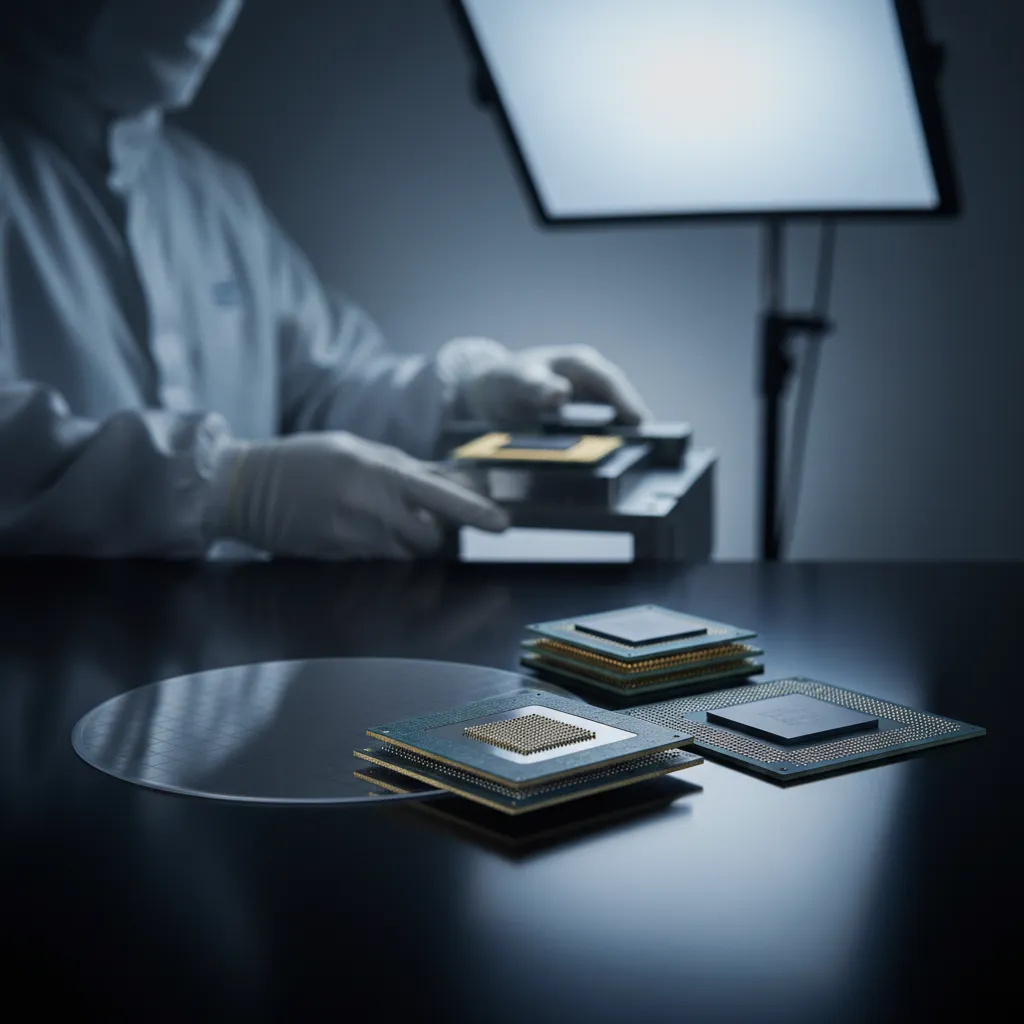
Advanced Packaging Design for Heterogeneous Integration
A high-density advanced package for an AI cloud processor now measures 55mm × 55mm or larger and stacks a 5-2-5 substrate — top 5 layers, middle 2, bottom 5 — scaling toward 11-2-11 wiring layers. At that scale, the design problem is no longer the die; it is how to interconnect partitioned chiplets densely, quickly, and reliably while holding cost in check. As device scaling slows, heterogeneous integration (HI) answers by letting designers choose the optimum process node for each function — 3nm for computing chiplets, 7nm for radio-frequency chiplets — and combine them in one package for higher functional density at lower cost per function.
The Interconnect Density Spectrum: FCBGA to 0.5μm/0.5μm
Not every chiplet link needs the same routing density, and matching density to need is the core design decision. ASE offers a spectrum of high-density packaging solutions — Flip Chip Ball Grid Array (FCBGA), Fan-Out Chip-on-Substrate (FOCoS), FOCoS-Bridge, and 2.5D — each occupying a different point on the line width/line spacing (L/S) curve:
- FCBGA interconnects chiplets through a BGA substrate at a minimum L/S of about 10μm/10μm.
- 2.5D (CoWoS-class) uses a redistribution layer (RDL) on a silicon interposer, pushing L/S down to 0.5μm/0.5μm — the highest density, but at a cost.
- FOCoS uses fan-out RDL to integrate chiplets at 2μm/2μm L/S, a lower-cost alternative for designs that don't require interposer-grade routing everywhere.
- FOCoS-Bridge embeds a silicon bridge for high-density routing only where high-speed transmission demands it, fanning out the rest — delivering both 0.5μm/0.5μm and 2μm/2μm flexibility in a single package.
The economics make the case for selectivity. In a 2.5D package, all chiplets sit side-by-side on the silicon interposer; as chiplet count rises, the interposer grows until fewer than 50 can be made from a 12-inch wafer — driving up cost sharply. FOCoS and FOCoS-Bridge let designers reserve the most expensive 0.5μm/0.5μm routing for the links that truly need it, dramatically improving the cost-versus-bandwidth trade-off.
High-Performance Chip-Package-System Co-Design
Achieving the bandwidth these packages promise requires designing the chip, package, and system together rather than as separate parts. Using electronic design automation (EDA) for holistic optimization, designers must account for signal change along the entire transmission path — copper pillar, RDL fine line, through silicon via (TSV), and microbump — and use eye diagrams to analyze the electrical performance of the SerDes link. When designing differential pairs for high-speed signals, the goal is to minimize return and insertion loss, especially within the operating frequency band. This end-to-end turnkey design capability, from chip to package to system, is where an integrated OSAT adds the most value.
Power Integrity: Moving Power Closer to the Die
As compute density rises, the industry is focused on energy efficiency — and a central question is whether power regulation and decoupling components, traditionally located on the system board, can move closer to the package or processor. There is active development around redesigning the on-chip power delivery network (PDN), including supplying power from the backside of the chip (backside PDN). Power integrity improves when decoupling capacitance sits as close to the die as possible: traditional surface-mount (SMT) capacitors are relatively large, but chip-level silicon capacitors (Si-Cap) now offer meaningful capacitance in a far smaller footprint, enabling tighter placement and cleaner power delivery.
UCIe: Standardizing the Chiplet Interface
Chiplet integration only scales if chiplets from different suppliers can interoperate. Historically, communication protocols existed at the chip and board level, but package-level integration needed its own standard. In March 2022, the UCIe (Universal Chiplet Interconnect Express) consortium formed to define a standardized data-transmission architecture for chiplet integration and reduce advanced-packaging design cost — and ASE is a founding Promoter member. ASE has developed packaging design specifications that integrate foundry specifications and the system requirements of OEMs and cloud service providers, helping realize ubiquitous chiplet heterogeneous integration across packaging architectures including 2.5D, 3D, FOCoS, fan-out, EMIB, and CoWoS.
Conclusion
Designing for heterogeneous integration means matching interconnect density to need across the full spectrum — FCBGA at 10μm/10μm, FOCoS at 2μm/2μm, and silicon-bridge or 2.5D routing at 0.5μm/0.5μm — while co-designing the chip, package, and system for signal and power integrity. As the world's largest outsourced semiconductor assembly and test (OSAT) provider, a UCIe founding member, and a supplier of one of the industry's broadest advanced-packaging portfolios, ASE offers a comprehensive one-stop service spanning design, packaging, and test — helping customers shorten chip design cycles and accelerate product innovation.
Explore advanced packaging design and the VIPack™ platform: See how ASE's chip-package-system co-design can accelerate your heterogeneous integration design at ase.aseglobal.com.
Frequently Asked Questions
Q: How large is a high-density advanced package for AI HPC? A: A typical AI cloud-processor package measures 55mm × 55mm or larger and uses a 5-2-5 advanced substrate (top 5 layers, middle 2, bottom 5), scaling toward 11-2-11 wiring layers, with chiplets interconnected by fan-out with silicon bridge or by 2.5D with a silicon interposer.
Q: What line width/line spacing (L/S) do ASE's packaging options achieve? A: FCBGA reaches about 10μm/10μm, FOCoS fan-out RDL reaches 2μm/2μm, and 2.5D (CoWoS-class) RDL on a silicon interposer reaches 0.5μm/0.5μm. FOCoS-Bridge combines 0.5μm/0.5μm and 2μm/2μm in one package.
Q: Why can 2.5D packaging be expensive? A: In 2.5D, all chiplets sit side-by-side on a silicon interposer. As chiplet count grows, the interposer enlarges until fewer than 50 can be produced from a 12-inch wafer, sharply increasing cost. FOCoS and FOCoS-Bridge reduce this by reserving fine routing only where needed.
Q: Why is chip-package-system co-design important? A: Bandwidth depends on the whole transmission path — copper pillar, RDL, TSV, and microbump. Co-design with EDA, eye-diagram analysis of SerDes links, and differential-pair optimization to minimize return and insertion loss are needed to achieve target performance.
Q: What is UCIe and what is ASE's role? A: UCIe (Universal Chiplet Interconnect Express) is a consortium formed in March 2022 to standardize chiplet interconnect at the package level and reduce design cost. ASE is a founding Promoter member, developing specifications across 2.5D, 3D, FOCoS, fan-out, EMIB, and CoWoS architectures.
✏️ AI 標題改寫建議
原始標題: Advanced Packaging Design for Heterogeneous Integration
建議標題: Advanced Packaging Design for HI: Matching Interconnect Density from FCBGA's 10μm to 0.5μm/0.5μm — and Why It Drives Cost
改寫理由: 原始標題已具搜尋關鍵字但偏籠統。建議標題以可量化的密度光譜(10μm → 0.5μm/0.5μm)與成本角度前置,更能吸引技術決策者。依 skill 規則 Ghost 標題沿用原名。
📊 改寫前後品質對比
| 指標 | 原始文章 | 改寫文章 | 變化 |
|---|---|---|---|
| 字數 | 1,041(單一大段) | ~1,350(分段敘事) | 重構 + 擴充 |
| 技術數據點 | 9 | 14 | +56% |
| H2 分段 | 內嵌、無實際分段 | 5 個 H2 | 改善 |
| 比較基準(L/S 光譜、wafer 經濟) | 部分 | 完整結構化 | 強化 |
| FAQ / JSON-LD / CTA | ✗ | ✓ | 新增 |
| 品質評分 | 6.5 / 10 | 9.2 / 10 | +2.7 |
原始文章 Original → Advanced Packaging Design for Heterogeneous Integration