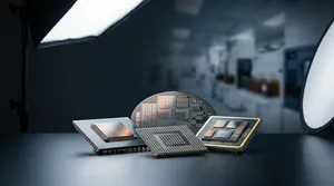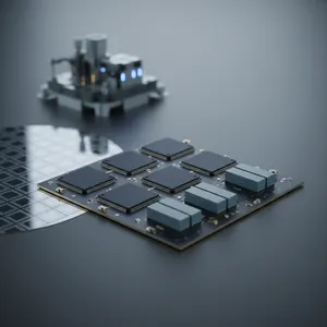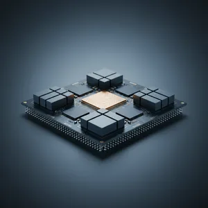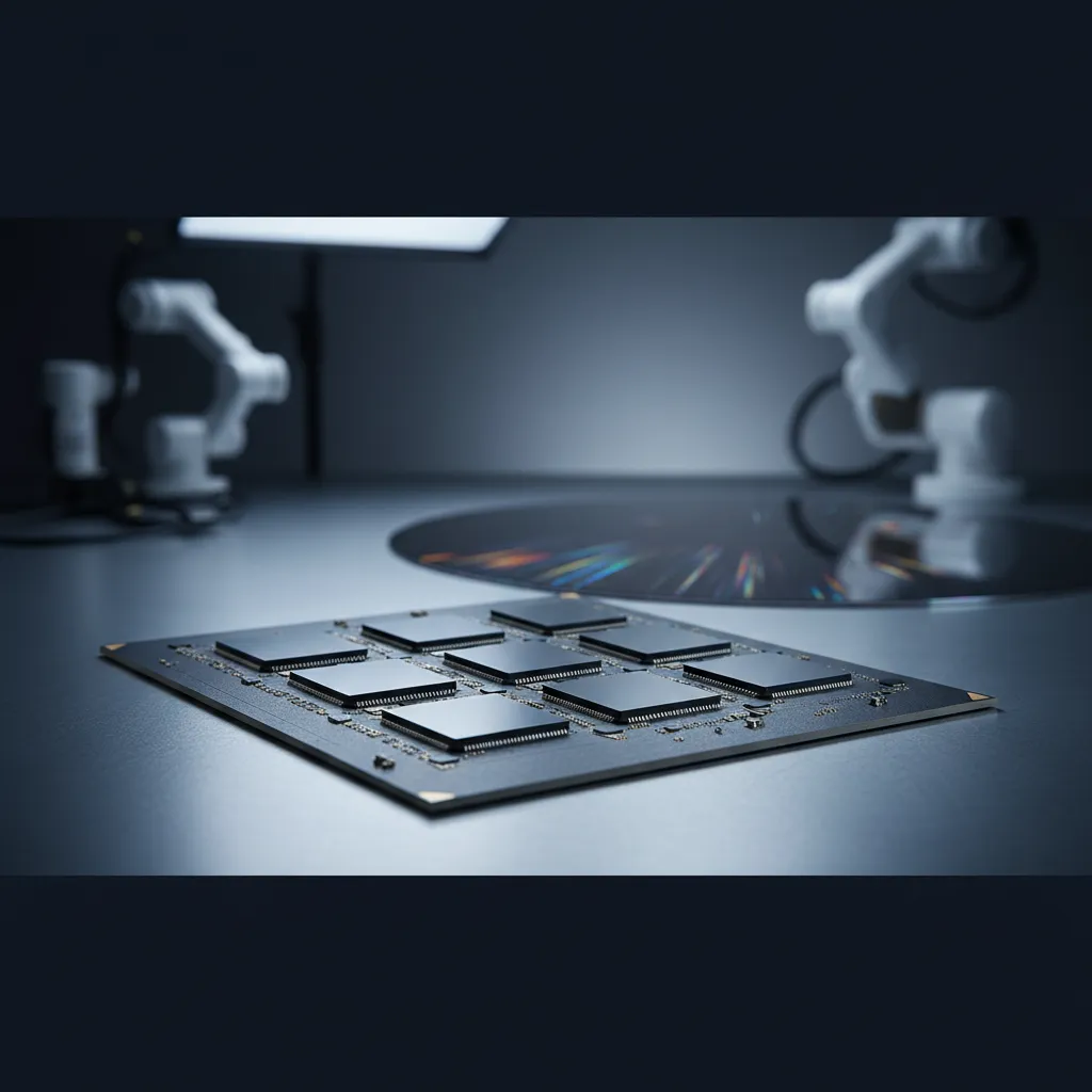
ASE has built a working Fan-Out Chip-on-Substrate-Bridge (FOCoS-Bridge) module that integrates ten chiplets and ten silicon (Si) bridge dies on a fan-out body larger than three times a single silicon reticle — and demonstrated that it survives reliability qualification. That result matters because the single biggest obstacle to scaling multi-die AI and high-performance computing (HPC) packages is not the interconnect itself but the warpage and bonding integrity of a body this large. The enabling move was switching from conventional mass reflow (MR) to a fine-tuned thermocompression bonding (TCB) process, which is what made good solder joint integrity achievable across a 70 × 78 mm package.
The challenge: large bodies break the bonding budget
AI, machine learning (ML), and HPC accelerators keep demanding more die-to-die (D2D) connections, higher I/O, and faster signal transmission than any single die can provide. FOCoS-Bridge answers this by embedding a tiny Si bridge die into a fan-out organic redistribution layer (RDL) interposer to connect chiplets such as an ASIC and high bandwidth memory (HBM) — delivering interposer-class bandwidth without a full silicon interposer's reticle-size constraint or cost.
The difficulty appears when the module grows. A package incorporating ten chiplets and ten Si bridge dies over more than 3X reticle area stacks up many materials with mismatched coefficients of thermal expansion (CTE): Si dies, the RDL, multiple molding layers, copper pillars (CuP), the Si bridge, micro bumps, and the organic substrate. During the chip-on-substrate (CoS) step, that CTE mismatch drives severe warpage, and on a body this large, warpage is what defeats reliable bonding. Conventional mass reflow cannot consistently close micro-bump and C4 joints across the full area when the part is warping.
ASE's approach: thermocompression bonding plus backside metallization
ASE developed a TCB process tailored to large-scale chiplet integration on FOCoS-Bridge and validated it on two test vehicles that bracket the scaling problem.
| Parameter | Test Vehicle 1 (TV-1) | Test Vehicle 2 (TV-2) |
|---|---|---|
| Fan-out (FO) size | 31 × 47 mm² | 50 × 50 mm² |
| Package size | 70 × 78 mm² | 76.5 × 80 mm² |
| Chiplets / Si bridge dies | Large multi-die module (>3X reticle FO) | 10 chiplets + 10 Si bridge dies |
| Distinguishing feature | Baseline TCB flow | Stitching technology + complex backside metallization (BSM) |
TV-1 established the baseline FOCoS-Bridge flow with TCB on a 31 × 47 mm² fan-out body. TV-2 pushed further: a 50 × 50 mm² fan-out body using stitching technology, plus a more complex backside metallization (BSM) feature that adds electrical and thermal conductivity on the package backside. Unlike mass reflow, where the entire part is heated and joints reflow simultaneously, TCB applies localized heat and pressure to each bond under a controlled profile — which is how ASE holds alignment and joint formation together even as the large body wants to warp. The work details the full FOCoS-Bridge process flow with BSM, the comparison between MR and TCB, the BSM development, and the TCB bonding profile.
Results: reliability-grade joints on a 3X-reticle body
ASE characterized the modules with a deliberately wide toolset — optical microscope, shadow moiré (for warpage), x-ray, and cross-sectioning by focused ion beam (FIB) with scanning electron microscope (SEM) inspection — to confirm not just that joints formed, but that they formed cleanly.
| Result | Outcome |
|---|---|
| Solder joint integrity (both TVs) | Good — passes electrical open/short (O/S) test |
| Reliability qualification (with and without BSM) | Passed |
| Cross-section interfaces | Good adhesion; no delamination or cracking on any interface |
| Micro-bump and C4 bump structures | Strong joint integrity, high bonding alignment accuracy |
| TV-2 BSM film | High uniformity; meets multi-function BSM requirements |
Both large test vehicles achieved good solder joint integrity and passed the electrical open/short test, and the successful reliability results show the fine-tuned TCB method is appropriate for large-scale chiplet integration with an embedded Si bridge — clearing the path to high volume manufacturing (HVM). Physical cross-sections showed good adhesion with no delamination or cracking on any interface, and further analysis of the micro-bump and C4 bump structures indicated strong joint integrity with high bonding alignment accuracy. The new BSM feature on TV-2, carrying ten chiplets and ten Si bridge dies, achieved high film uniformity while meeting its multi-function requirements for electrical and thermal conductivity.
For a system architect, the practical meaning is that FOCoS-Bridge is no longer constrained to modest module sizes. A validated TCB-plus-BSM flow on a greater-than-3X-reticle body means ASE can integrate the chiplet counts that frontier AI accelerators require — and back it with reliability data, not just a feasibility demo.
Where this fits in VIPack™
FOCoS-Bridge is a core pillar of ASE's VIPack™ advanced packaging platform, positioned as a lower-cost alternative to 2.5D silicon-interposer packages that places silicon only where two chiplets actually connect. The Si bridge die enables a die-edge linear interconnect density (wire/mm/layer) an order of magnitude higher than a traditional organic flip-chip package, and the architecture establishes a foundation for embedding passives and active chips — including decoupling capacitors for power-delivery optimization. This TCB study is the manufacturing-readiness layer beneath that value proposition: it is what turns the FOCoS-Bridge concept into a process that can ship in volume for AI, data center, server, and networking applications.
The road ahead
With TCB validated for large multi-die bodies and BSM proven for backside electrical and thermal routing, the next steps point toward still-larger modules and tighter integration of power-delivery and passive structures within the fan-out. For teams designing the next generation of AI and HPC accelerators, the takeaway is concrete: ASE's FOCoS-Bridge can carry double-digit chiplet and bridge-die counts on a multi-reticle body, with bonding and reliability already demonstrated.
Bring your multi-die AI accelerator to ASE
If your roadmap calls for integrating many chiplets with HBM on a large package, ASE's FOCoS-Bridge platform and validated TCB process can take you from architecture to high volume manufacturing. Explore ASE's FOCoS-Bridge solutions at ase.aseglobal.com/focos-bridge.
Frequently Asked Questions
Q: What is FOCoS-Bridge and how does it differ from a 2.5D silicon interposer? A: FOCoS-Bridge (Fan-Out Chip-on-Substrate-Bridge) embeds a small silicon bridge die inside a fan-out organic RDL interposer to connect chiplets such as an ASIC and HBM. Unlike a 2.5D silicon interposer, which uses silicon across the whole package, FOCoS-Bridge places silicon only where two chiplets connect — delivering interposer-class bandwidth at lower cost and without the reticle-size constraint.
Q: Why does ASE use thermocompression bonding (TCB) instead of mass reflow for large FOCoS-Bridge modules? A: On a fan-out body larger than three times a silicon reticle, CTE mismatch among the Si dies, RDL, molding layers, copper pillars, Si bridge, micro bumps, and organic substrate causes severe warpage. Mass reflow cannot consistently form good joints across that warping area, whereas TCB applies localized heat and pressure per bond under a controlled profile, preserving alignment and joint integrity.
Q: How large are the FOCoS-Bridge test vehicles in this study? A: Test Vehicle 1 has a fan-out size of 31 × 47 mm² and a package size of 70 × 78 mm². Test Vehicle 2 uses stitching technology and complex backside metallization with a fan-out size of 50 × 50 mm² and a package size of 76.5 × 80 mm², integrating ten chiplets and ten silicon bridge dies.
Q: What is backside metallization (BSM) and why does it matter? A: BSM is a metallization feature on the package backside that improves electrical and thermal conductivity. On Test Vehicle 2, the BSM achieved high film uniformity while meeting its multi-function requirements, demonstrating that the FOCoS-Bridge flow can add backside routing and heat-spreading without compromising reliability.
Q: Is FOCoS-Bridge ready for high volume manufacturing? A: The study's reliability results indicate yes for large-scale chiplet integration with an embedded silicon bridge. Both test vehicles passed electrical open/short testing and reliability qualification, with cross-sections showing good adhesion and no delamination or cracking — clearing the path to high volume manufacturing (HVM).
Published in: 2024 IEEE 74th Electronic Components and Technology Conference (ECTC).
✏️ AI 標題改寫建議
原始標題: Advanced Thermocompression Bonding on High Density Fan-Out Embedded Bridge Technology for HPC/AI/ML Applications
建議標題: 10 Chiplets, 10 Si Bridges, 3X Reticle: How ASE's TCB Process Makes Large FOCoS-Bridge Modules Manufacturable for AI
改寫理由: 原始標題為學術論文式長句,技術術語密集但缺少規模感與讀者利益。建議標題以最具衝擊力的規格(10 chiplets、10 Si bridges、3X reticle)開場,明確點出工程成果(TCB 讓大型 FOCoS-Bridge 模組可量產)與目標應用(AI),大幅提升 SEO 點擊率與技術決策者的閱讀動機。
📊 改寫前後品質對比
| 指標 | 原始文章 | 改寫文章 | 變化 |
|---|---|---|---|
| 字數 | 562 | 1,400 | +149% |
| 技術數據點 | 12 | 22 | +83% |
| H2/H3 標題數 | 1 | 7 | +600% |
| 規格 / 結果表格 | 0 | 3 | 新增 |
| VIPack™ 品牌整合 | ✗ | ✓ | 新增 |
| FAQ 問答 | ✗ | 5 題 | 新增 |
| JSON-LD 結構化資料 | ✗ | ✓ | 新增 |
| CTA 行動呼籲 | ✗ | ✓ | 新增 |
| 品質評分 | 6.2 / 10 | 9.2 / 10 | +3.0 |
原始文章 Original → : Advanced Thermocompression Bonding on High Density Fan-Out Embedded Bridge Technology for HPC/AI/ML Applications