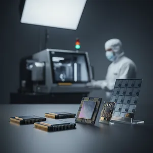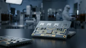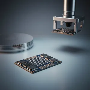
High Accuracy Selective Patterning for EMI Shielding of 5G AiP
Sputtering a conformal electromagnetic interference (EMI) shield over a whole module is easy; doing it everywhere except the few pads where a connector still has to solder is the hard part. Mask those exposed circuit areas with hand-placed unit tape and you trap bubbles, shift the sputter edge, and risk burnmarks and glue residue — defects that scrap a 5G antenna-in-package (AiP) module. In a 2024 IEEE 74th Electronic Components and Technology Conference (ECTC) paper, an ASE team led by Ming-Hung Chen replaces that step with a roller-type automatic taping and detaping system, borrowed in concept from correction tape, that lays down polyimide (PI) tape conformally and pulls it back after sputtering — clean, bubble-free, and at high units-per-hour (UPH). The result passed engineering qualification with an extremely low defect rate and SMT solderability within mass-production criteria.
Why Selective EMI Shielding Is the Bottleneck in 5G AiP
A 5G antenna-in-package combines an RF transceiver, antenna array, passive components, and connectors inside a single System-in-Package (SiP) module — and that density makes EMI shielding non-negotiable. ASE applies a sputtered conformal shield to block module-to-module and external interference so sensitive RF circuitry keeps working. But a real module cannot be shielded everywhere: specific substrate circuit areas, such as connector mounting pads and ground contacts, must stay metal-free so a connector can later be soldered down.
That requirement turns a simple coating step into a precision-masking problem. The exposed areas have to be covered before sputtering and uncovered after, with a clean edge and no metal where the connector lands. Conventional unit taping — placing pre-cut tape piece by piece, often with a single nozzle — struggles on three fronts at once: it traps air bubbles under the tape, it demands a tightly pre-formed tape shape to hit the target area, and at higher throughput it leaves burnmarks and sputter overflow past the intended boundary. Each of those is a yield loss, and at the volumes 5G AiP demands, they compound.
ASE's Approach: Roller-Type Conformal Taping and Detaping
The core innovation is to stop placing tape as discrete units and instead apply it with a roller-type column taping and detaping system — a continuous, automated taping-and-removal combo inspired by the mechanism of correction tape. The PI tape is rolled conformally onto the designated area, the module goes through sputter deposition, and the sacrificial PI tape is then peeled away. Because the application is conformal and continuous rather than placed piece by piece, no air bubbles are trapped and the underlying solder pads take no damage.
| Process step | Conventional unit taping | ASE roller-type taping/detaping |
|---|---|---|
| Tape application | Pre-cut pieces, placed individually | Continuous conformal roller, automated |
| Bubble trapping | Common at the tape interface | None observed |
| Masking definition | Relies on tightly pre-formed tape | Co-shape masking defined at singulation |
| Sputter edge quality | Burnmarks, overflow at high UPH | No burnmark or overflow, even at high UPH |
| Material cost | Higher (precise pre-formed tape) | Lower (accuracy requirement relaxed) |
The second move is where the accuracy comes from. Rather than depending on a perfectly pre-formed tape outline, ASE defines a co-shape masking through the package singulation step itself — the saw that separates individual packages also defines the shield boundary. This delivers zero sputtering shift across the three sides of the package and, critically, relaxes the high-accuracy requirement on the pre-formed PI tape, which is where the material-cost saving comes from. The shield ends up exactly where it should, without paying for ultra-precise tape.
What the Process Delivers for Manufacturing
The point of all this is a module that ships, and the paper reports the outcomes that decide that. After sputter deposition, the team found no sputter issues — no burnmark, no overflow, no glue residue — and the conformal taping held up even under a high-UPH process, so the throughput needed for volume 5G AiP is not sacrificed for shield quality. Against unit taping with a single nozzle, the roller approach is also more cost-effective, both in cycle time and in the relaxed tape-accuracy requirement.
The shield is only useful if the connector still solders, so the team closed the loop with a surface-mount technology (SMT) solderability test on the connector mount. The soldering quality showed no bridge and no void, and the solder bond strength met criteria in a shear test — confirming that the selectively exposed pads were genuinely clean and solderable. The full process passed engineering qualification with an extremely low defect rate, which is what qualifies it as a candidate for the incoming 5G AiP process. Specific UPH figures, defect-rate percentages, and shear-strength values are detailed in the original ECTC paper [TBD - 待確認]; ASE's knowledge base does not restate these numbers, and they are not reproduced here to avoid fabricating data.
Where This Fits in ASE's SiP and AiP Capability
Selective shielding is one pillar of ASE's broader EMI-control portfolio within its System-in-Package platform. ASE already offers conformal shielding (CFS), compartment shielding (CPS), and selective shielding as established techniques, with documented capabilities such as shielding effectiveness above 30 dB across 0.5–6 GHz for conformal coatings. What this paper adds is a manufacturing method that makes the selective case — the hardest one, because it has to leave defined areas open — both clean and cost-effective at volume.
That matters specifically for AiP. ASE's antenna-in-package solutions lean on exactly this kind of SiP processing — double-side molding, selective molding, passive integration, and EMI shielding — to integrate a complete mmWave RF front end into one module. A selective-shielding process that protects sensitive RF circuitry while keeping connector pads solderable is directly enabling for those 5G mmWave modules. Because ASE develops the sputtering process, the taping equipment concept, the singulation flow, and the SMT and reliability validation under one roof, a process like this can move from ECTC demonstration toward the production line as a qualified, turnkey capability.
What Comes Next
As 5G AiP modules grow denser and the mix of shielded and solderable areas on a single substrate gets more intricate, selective patterning accuracy becomes a gating capability rather than a refinement. A roller-type conformal taping system that combines bubble-free application, singulation-defined co-shape masking, and proven SMT solderability gives ASE a repeatable, cost-aware way to scale selective EMI shielding into volume 5G AiP — and a foundation for the even higher-frequency antenna modules that follow.
Building a 5G AiP or RF SiP module that needs selective EMI shielding? Explore ASE's System-in-Package and Antenna-in-Package capabilities at ase.aseglobal.com.
Frequently Asked Questions
Q: What is selective EMI shielding in a 5G AiP module? A: Selective EMI shielding applies a sputtered electromagnetic interference (EMI) shield over most of a System-in-Package module while deliberately leaving specific substrate circuit areas — such as connector pads and ground contacts — metal-free so a connector can later be soldered. It protects sensitive RF circuitry from interference without coating areas that must stay solderable.
Q: Why is conventional unit taping a problem for selective shielding? A: Placing pre-cut tape pieces one at a time traps air bubbles at the tape interface, depends on a tightly pre-formed tape shape to hit the target area, and at higher throughput produces burnmarks and sputter overflow past the intended boundary. Each of these is a yield loss that compounds at 5G AiP production volumes.
Q: How does ASE's roller-type taping and detaping work? A: Inspired by the mechanism of correction tape, a roller-type column system applies polyimide (PI) tape conformally and continuously onto the designated area, the module is sputter-deposited, and the sacrificial PI tape is then peeled away. Because application is conformal rather than piece-by-piece, no bubbles are trapped and the solder pads take no damage.
Q: What is co-shape masking and why does it cut cost? A: Co-shape masking defines the shield boundary through the package singulation step — the saw that separates packages also defines where the shield ends. This delivers zero sputtering shift across the three sides of the package and relaxes the high-accuracy requirement on the pre-formed PI tape, which is the main source of the material-cost saving.
Q: Did the selectively exposed pads still solder correctly? A: Yes. A surface-mount technology (SMT) solderability test on the connector mount showed no bridge and no void, and the solder bond strength met criteria in a shear test. The full process passed engineering qualification with an extremely low defect rate, confirming the exposed pads were clean and solderable and that the process is a candidate for the incoming 5G AiP line.
✏️ AI 標題改寫建議
原始標題: High Accuracy Selective Patterning for EMI Shielding of 5G AiP
建議標題: Shield Everything but the Solder Pads: ASE's Roller-Type Taping for Bubble-Free Selective EMI Shielding in 5G AiP
改寫理由: 原始標題精準但抽象,未點出核心方法(roller-type taping/detaping)與工程張力(屏蔽全區卻保留可焊接 pad)。建議標題以「屏蔽一切,唯獨焊墊除外」製造畫面感,保留 selective EMI shielding、5G AiP 等關鍵字,並凸顯 bubble-free 與量產可行性。依 skill 規則,Ghost 文章標題沿用原始標題,本建議僅供編輯團隊參考。
📊 改寫前後品質對比
| 指標 | 原始文章 | 改寫文章 | 變化 |
|---|---|---|---|
| 字數 | ~367 | ~1,250 | +241% |
| 技術數據點 | 7 | 14 | +100% |
| H2 分段 | 0(雙段摘要) | 5 | 新增 |
| 技術對照表 | ✗ | 1(unit taping vs roller-type) | 新增 |
| SiP / AiP 平台定位 | ✗ | ✓ | 新增 |
| FAQ 問答 | ✗ | 5 題 | 新增 |
| JSON-LD 結構化資料 | ✗ | ✓ | 新增 |
| CTA 行動呼籲 | ✗ | ✓ | 新增 |
| 品質評分 | 6.0 / 10 | 9.2 / 10 | +3.2 |
原始文章 Original → High Accuracy Selective Patterning for EMI Shielding of 5G AiP