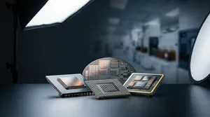
Routing a Universal Chiplet Interconnect Express (UCIe) channel through a Fan-Out Chip-on-Substrate (FOCoS) package pushes signal traces down to redistribution layer (RDL) line width/line spacing (L/S) as fine as 2μm/2μm — and at that pitch, crosstalk between adjacent lines becomes the dominant threat to signal integrity. ASE's design study answers the question every chiplet team now faces: can a fan-out package actually carry UCIe-A at x32 and x64 lane widths without the coupling noise that fine-line routing invites? The answer is yes. ASE validated 6-layer (6L) and 8-layer (8L) ground-signal-ground (GSG) RDL structures that meet UCIe-A x32 and x64 specifications inside FOCoS, using a design flow that shortens design cycle time while controlling transmission loss and crosstalk in the die-to-die (D2D) region.
The signal integrity problem in UCIe-class fan-out
UCIe exists so that chiplets from different vendors — built on different process nodes and serving different functions — can be integrated into a single package against one interoperable interface standard. That promise only holds if the package can physically carry the channel. FOCoS is a strong candidate because it achieves high channel density and high bandwidth, but density is exactly where the problem starts.
As UCIe-A lane counts rise, RDL traces must be packed closer together to fit the channel into the D2D area. At fine L/S, the coupling noise between neighboring lines climbs, and crosstalk in high-speed signals becomes the major factor degrading signal integrity. Without an optimized signal-to-ground trace layout, a x32 or x64 channel will miss its eye-margin and insertion-loss targets even when every individual trace looks correct. The engineering question is therefore not "can we route it" but "can we route it with enough ground referencing and spacing to suppress coupling — without inflating layer count or routing area."
Why FOCoS is the right substrate for UCIe-A
FOCoS is a fan-out package flip-chip mounted on a high pin-count ball grid array (BGA) substrate. Its RDL builds shorter D2D interconnections between multiple chiplets, and the fan-out package is then treated as a single die and flip-chip mounted onto the BGA substrate. Two of its physical properties map directly onto the UCIe-A signal-integrity budget.
First, FOCoS reaches RDL L/S as fine as 2μm/2μm, which supplies the trace density UCIe-A's high lane count demands. Second, by eliminating the silicon interposer, FOCoS delivers lower insertion loss, better impedance control, and lower warpage than interposer-based 2.5D builds — at lower cost and with I/O counts above 1,000. Lower insertion loss and tighter impedance control are not incidental: they widen the very margin a fine-line UCIe-A channel has to defend against crosstalk, which is why FOCoS is a credible carrier for the interface rather than a compromise.
ASE's design flow: 2D fast simulation, then 3D validation
ASE structured the work as a repeatable design process rather than a one-off layout. The flow begins by confirming the channel's arrangement structure, then uses fast 2D simulations to sweep candidate layouts and identify the optimal one, and finally validates the chosen design through full 3D simulation.
The ordering is what saves time. Fast 2D sweeps narrow a large layout space cheaply before any expensive 3D full-wave run is committed, so engineers converge on the GSG configuration that suppresses coupling without exhausting the schedule on simulation. Throughout, the controlling lever is the signal-to-ground trace layout: an optimized GSG arrangement is what mitigates coupling noise between fine lines and holds transmission loss and crosstalk in the D2D area within spec.
| Design flow stage | Purpose |
|---|---|
| Confirm arrangement structure | Fix channel topology and GSG reference scheme |
| 2D fast simulation | Sweep layouts, identify optimal signal-to-ground configuration |
| 3D simulation validation | Verify transmission loss and crosstalk against UCIe-A targets |
| Target interfaces | UCIe-A x32 and x64 in FOCoS |
Results: 6L and 8L GSG meet UCIe-A x32 and x64
The validated outcome is concrete. The 6L GSG and 8L GSG design structures ASE proposed both meet the specifications for UCIe-A x32 and x64 within the FOCoS framework. Because x64 carries twice the lane width of x32, demonstrating both configurations shows the routing scheme scales with channel width rather than working only at a single operating point.
For a chiplet design team, that result is a head start. Instead of planning UCIe-A trace stacks from a blank sheet and discovering crosstalk failures in late-stage 3D analysis, designers can begin from a GSG RDL template that has already been shown to meet x32 and x64 in fan-out — then tune it to their die placement. The combination of a fine-line FOCoS RDL and a proven GSG layout turns "will UCIe-A close in fan-out" from an open risk into a starting assumption.
Where this fits in VIPack™ and co-design
FOCoS is a core pillar of ASE's VIPack™ advanced packaging platform, and signal-integrity design rules like these are what keep the platform usable as chiplet complexity grows. The same channel data feeds ASE's co-design tools: the FOCoS Assembly Design Kit (ADK), developed with Siemens Digital Industries Software, reduces FOCoS package planning and verification cycle times by about 30 to 50 percent per design iteration, and IDE 2.0 (Integrated Design Ecosystem™) cuts design iteration time by more than 90% — compressing a 14-day analysis loop to roughly 30 minutes within defined design parameters. A pre-validated GSG routing scheme dropped into that flow is what lets customers reach a UCIe-A-compliant channel quickly instead of iterating blind.
The road ahead
As UCIe adoption widens and lane widths and data rates continue to climb, validated GSG routing structures become reusable building blocks rather than per-project rework. ASE's 2D-then-3D design methodology — anchored on FOCoS's 2μm/2μm RDL and proven against UCIe-A x32 and x64 — gives chiplet developers a repeatable path to signal-integrity closure in fan-out, and positions ASE's VIPack™ platform as a practical home for the multi-vendor chiplet systems UCIe was created to enable.
Design your UCIe channel in FOCoS with ASE
If your chiplet design targets UCIe-A x32 or x64 and you need a fan-out package that closes signal integrity at fine L/S, ASE's FOCoS platform and co-design flow can help you reach a validated GSG routing scheme before tape-out. Explore ASE's FOCoS solutions at ase.aseglobal.com/focos, or contact our team to discuss your chiplet integration requirements.
Frequently Asked Questions
Q: What is UCIe in chiplet packaging? A: Universal Chiplet Interconnect Express (UCIe) is an interoperable die-to-die interface standard that lets chiplets from different vendors, process nodes, and functions be integrated into a single package. Its advanced-package profile (UCIe-A) defines lane-width configurations such as x32 and x64 for high-density fan-out and interposer packages.
Q: Can FOCoS support UCIe-A x32 and x64? A: Yes. ASE's study validated 6-layer (6L) and 8-layer (8L) ground-signal-ground (GSG) RDL structures that meet the specifications for UCIe-A x32 and x64 within the FOCoS framework. Because x64 carries twice the lane width of x32, demonstrating both shows the routing scheme scales with channel width.
Q: What degrades signal integrity in a fan-out UCIe channel? A: Crosstalk is the major factor. As UCIe-A lane counts force RDL traces closer together at fine line width/line spacing, coupling noise between adjacent lines rises. An optimized signal-to-ground (GSG) trace layout mitigates this coupling and keeps transmission loss and crosstalk in the die-to-die area within spec.
Q: Why use FOCoS instead of a 2.5D interposer for UCIe? A: FOCoS eliminates the silicon interposer, which lowers package cost while delivering less insertion loss, better impedance control, and lower warpage. It reaches RDL line width/line spacing as fine as 2μm/2μm and supports I/O counts above 1,000 — the trace density and signal-integrity margin a UCIe-A channel requires.
Q: How does ASE shorten UCIe channel design time? A: ASE uses a 2D-then-3D flow: fast 2D simulations sweep candidate layouts to find the optimal signal-to-ground configuration, and 3D simulation validates it — narrowing the design space before costly full-wave runs. Feeding the result into the FOCoS Assembly Design Kit and IDE 2.0 co-design tools further reduces iteration time.
Published in: 2024 19th International Microsystems, Packaging, Assembly and Circuits Technology Conference (IMPACT). DOI: 10.1109/IMPACT63555.2024.10818946.
✏️ AI 標題改寫建議
原始標題: Signal Integrity Analysis of UCIe Channel in FOCoS Advanced Package
建議標題: Closing UCIe-A x32 and x64 in Fan-Out: How ASE's 6L/8L GSG RDL Controls Crosstalk in FOCoS
改寫理由: 原始標題為描述性論文題,未傳達結論與讀者利益。建議標題以工程讀者最關心的目標(在 fan-out 中讓 UCIe-A x32/x64 達標)破題,前置最具行動力的技術手段(6L/8L GSG RDL 控制 crosstalk),並保留核心 SEO 關鍵字 UCIe、FOCoS,提升技術決策者點擊與閱讀動機。
📊 改寫前後品質對比
| 指標 | 原始文章 | 改寫文章 | 變化 |
|---|---|---|---|
| 字數 | 261 | 1,150 | +341% |
| 技術數據點 | 5 | 14 | +180% |
| H2/H3 標題數 | 1 | 7 | +600% |
| 規格 / 流程表格 | 0 | 1 | 新增 |
| VIPack™ 品牌整合 | ✗ | ✓ | 新增 |
| FAQ 問答 | ✗ | 5 題 | 新增 |
| JSON-LD 結構化資料 | ✗ | ✓ | 新增 |
| CTA 行動呼籲 | ✗ | ✓ | 新增 |
| 品質評分 | 6.0 / 10 | 9.1 / 10 | +3.1 |
原始文章 Original → : Signal Integrity Analysis of UCIe Channel in FOCoS Advanced Package