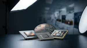
When a design team chooses an interconnect platform for an ASIC-plus-high bandwidth memory (HBM) package, the decision usually comes down to a trade-off between bandwidth and cost. The conventional assumption is that a TSV-based silicon interposer (2.5D IC) is the safe high-performance choice, while redistribution layer (RDL) fan-out is the cost play. ASE's finite element analysis (FEA) of three competing package builds — 2.5D IC, chip-first Fan-Out Chip-on-Substrate (FOCoS), and chip-last FOCoS — complicates that assumption. The study found that both FOCoS variants exhibit lower package warpage and lower extreme-low-k (ELK) dielectric stress than 2.5D IC, while delivering comparable board-level reliability and thermal performance. For designers, that means the lower-cost fan-out route does not necessarily carry a reliability penalty.
The challenge: bandwidth demand meets interposer cost
Networking switches, AI compute, and GPU silicon are all pushing toward higher bandwidth and pin counts than a single monolithic die can economically deliver. Heterogeneous integration answers this by connecting multiple dies through fine line/space interconnect, and two platforms dominate the high-bandwidth tier: TSV interposer technology, used in 2.5D IC packaging, and RDL fan-out, better known as FOCoS.
The two routes solve the same problem with very different cost structures. A 2.5D silicon interposer with through silicon via (TSV) reaches extreme routing density — line width/line spacing (L/S) down to 0.4μm/0.4µm and over 400 µbumps/mm² — but adds a costly silicon interposer layer and is bounded by reticle size. FOCoS instead builds shorter die-to-die (D2D) interconnects on an RDL (L/S as fine as 2μm/2μm) and flip-chip mounts the reconstituted fan-out package onto a high-pin-count BGA substrate, eliminating the interposer entirely. The open engineering question this paper set out to answer is whether removing the interposer compromises mechanical or thermal reliability.
ASE's approach: a validated multi-physics comparison
Rather than rely on rules of thumb, ASE built three-dimensional numerical models of all three package types and ran them through FEA for mechanical and thermal-mechanical behavior, then through computational fluid dynamics (CFD) for heat dissipation. The models were not left unvalidated: warpage and thermal-mechanical deformation predicted for chip-last FOCoS were checked against physical measurements from an advanced Metrology Analyzer (aMA) system, anchoring the simulation to real hardware before it was used to draw comparisons.
| Package type | Interconnect route | Key structural feature |
|---|---|---|
| 2.5D IC | TSV silicon interposer | Highest routing density; interposer adds cost and reticle limit |
| Chip-first FOCoS | RDL fan-out (chip placed before RDL) | No interposer; RDL/PI buffer layers |
| Chip-last FOCoS | RDL fan-out (RDL built first) + wafer-level underfill | No interposer; wafer-level underfill controls warpage |
With the model validated, the team examined four reliability-critical responses across the three builds: package warpage, ELK dielectric layer stress, board-level solder joint reliability under thermal cycling, and D2D copper trace stress — the last specifically as a function of chip-last FOCoS wafer-level underfill material properties.
Results: fan-out is not the reliability compromise it is assumed to be
The simulation produced several findings that run against the default "interposer = safer" intuition.
| Reliability metric | 2.5D IC | Chip-first FOCoS | Chip-last FOCoS |
|---|---|---|---|
| Package warpage | Highest | Lower than 2.5D | Lowest |
| ELK layer stress | Highest | Lower than 2.5D | Lower than 2.5D |
| Board-level TCT (solder joint) | Similar | Similar | Similar |
| D2D copper trace stress | Lowest | Higher | Higher |
Both FOCoS variants show lower warpage than 2.5D IC, because the coefficient of thermal expansion (CTE) mismatch between the combo die and the stack-up substrate is smaller in the fan-out construction. Chip-last FOCoS records the lowest warpage of all, a result attributable to its wafer-level underfill. ELK stress follows the same direction: both FOCoS builds keep ELK dielectric stress below 2.5D IC, because the RDL and polyimide (PI) layers act as an effective buffer that absorbs stress before it reaches the fragile low-k dielectric.
Board-level reliability is effectively a wash. The maximum creep strain energy density (CSED) occurs on the outermost solder joint at the package edge, on the substrate-side top surface, in all three builds — and the difference in CSED between them is insignificant. Because the equivalent CTE of all three package types is similar, their board-level thermal cycling test (TCT) performance is comparable. The one metric favoring 2.5D IC is D2D copper trace stress, which is lowest in the interposer build owing to its smaller localized CTE mismatch.
That copper trace result also points to the design lever for fan-out. Among the wafer-level underfill candidates, type D — with higher glass transition temperature (Tg) and lower CTE — produced the lowest copper trace stress, which translates directly into better D2D trace reliability. In other words, underfill material selection, not the interposer, is the dominant knob for trace reliability in chip-last FOCoS. On heat dissipation, the CFD results show all three package types perform similarly and all are adequate for high-power applications.
Where this fits in VIPack™
These findings are part of the engineering foundation under ASE's VIPack™ platform, where FOCoS and TSV-based 2.5D/3D IC sit side by side as complementary pillars rather than competitors. The study's practical message — that FOCoS delivers interposer-comparable reliability while eliminating interposer cost — is exactly why FOCoS is positioned for large, high-I/O (greater than 1,000 I/O) networking and server packages, with chip-last FOCoS extending to ASIC-plus-HBM integration for high-performance computing (HPC) and AI/ML workloads. For programs where maximum routing density is non-negotiable, the platform's 2.5D/3D IC route remains available. ASE's design enablement, including its FOCoS Assembly Design Kit, lets teams evaluate these trade-offs before committing to physical design.
The road ahead
This 2020 comparative study established a baseline that later ASE research has built on, extending FOCoS toward embedded silicon bridges (FOCoS-Bridge) and finer RDL stacks for higher bandwidth. For a designer choosing a platform today, the takeaway holds: treat the interposer as a cost and reticle decision, not an automatic reliability upgrade, and use validated simulation plus underfill selection to close the gap where it matters.
Evaluate FOCoS for your next ASIC + HBM package
If you are weighing 2.5D IC against fan-out for a high-bandwidth design, ASE's FOCoS portfolio and design kits can help you model the warpage, ELK stress, and trace-reliability trade-offs before tape-out. Explore ASE's FOCoS solutions at ase.aseglobal.com/focos.
Frequently Asked Questions
Q: What is the difference between 2.5D IC and FOCoS packaging? A: 2.5D IC places dies side by side on a TSV silicon interposer, reaching extreme routing density (L/S down to 0.4μm/0.4µm) but adding interposer cost and a reticle-size limit. FOCoS (Fan-Out Chip-on-Substrate) builds shorter die-to-die interconnects on a redistribution layer (L/S as fine as 2μm/2μm) and flip-chip mounts the fan-out package onto a BGA substrate, eliminating the interposer to lower cost.
Q: Does removing the silicon interposer hurt package reliability? A: According to ASE's FEA study, no — both chip-first and chip-last FOCoS show lower package warpage and lower ELK dielectric stress than 2.5D IC, and all three builds deliver comparable board-level thermal cycling reliability and heat dissipation. The main metric favoring 2.5D IC is die-to-die copper trace stress.
Q: What is the difference between chip-first and chip-last FOCoS? A: In chip-first FOCoS the dies are placed before the redistribution layer is built; in chip-last FOCoS the RDL is built first and the dies are attached afterward, with a wafer-level underfill step. The study found chip-last FOCoS achieves the lowest warpage of the three package types, largely because of that wafer-level underfill.
Q: How does underfill material affect FOCoS reliability? A: Wafer-level underfill is the dominant lever for die-to-die copper trace reliability in chip-last FOCoS. The study found that a type-D underfill with higher glass transition temperature (Tg) and lower CTE produced the lowest copper trace stress, improving trace reliability.
Q: Which applications is FOCoS best suited for? A: FOCoS is ideal for large package sizes with high I/O density (greater than 1,000 I/O) in networking and server applications. Chip-last FOCoS is well suited to packaging ASICs together with high bandwidth memory (HBM) for high-performance computing (HPC) and AI/ML workloads.
Published in: 2020 IEEE Electronic Components and Technology Conference (ECTC) — "A comparative study of 2.5D and fan-out chip on substrate: Chip first and chip last."
✏️ AI 標題改寫建議
原始標題: 2.5D vs Fan-out Chip on Substrate
建議標題: 2.5D IC vs. FOCoS: FEA Data Shows Fan-Out Cuts Warpage and ELK Stress Without an Interposer
改寫理由: 原始標題僅點出比較主體,缺少結論與數據誘因。建議標題保留核心對比(2.5D vs FOCoS),並前置最具差異性的研究結論(fan-out 降低 warpage 與 ELK stress 且無需 interposer),同時以「FEA Data Shows」強化可信度與 E-E-A-T,提升技術讀者的點擊意願。
📊 改寫前後品質對比
| 指標 | 原始文章 | 改寫文章 | 變化 |
|---|---|---|---|
| 字數 | 509 | 1,320 | +159% |
| 技術數據點 | 6 | 18 | +200% |
| H2/H3 標題數 | 1 | 7 | +600% |
| 規格 / 結果表格 | 0 | 2 | 新增 |
| VIPack™ 品牌整合 | ✗ | ✓ | 新增 |
| FAQ 問答 | ✗ | 5 題 | 新增 |
| JSON-LD 結構化資料 | ✗ | ✓ | 新增 |
| CTA 行動呼籲 | ✗ | ✓ | 新增 |
| 品質評分 | 6.0 / 10 | 9.1 / 10 | +3.1 |
原始文章 Original → : 2.5D vs Fan-out Chip on Substrate